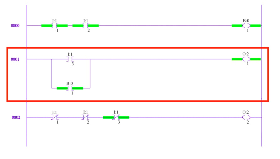
Programmable Logic Controllers ( PLC ). One of the best visual programming languages is a PLC programming language. It’s called ladder logic or ladder diagram (LD) and you can learn it very fast. Ladder logic was originally a written method to document the design and construction of relay racks as used in manufacturing and process control. Each device in the relay rack would be represented by a symbol on the ladder diagram with connections between those devices shown.

Their ability to accept programming in ladder diagram format is one of the reasons for the success of programmable logic controllers (PLCs) in the industry. More available at instrumentationtools. Ladder diyagramı ile ilgili bildiğin bir kitap var mı?
Bu sebeple, bir an önce öğrenmem lazım. IMPORTANT:- In the video, there are two vertical straight lines of Ladder Diagram , called as Power Rails. While explaining by mistake I named it as Power Trails. After watching this video you will.

Birkaç istisna dışında bir formatta yazılmış bir program başka bir formatta görülebilir. This is a graphical language showing the logical relationships between inputs and outputs as though they were contacts and coils in a hard-wired electromechanical relay circuit. Cevapla bu yapılanları hangi programda yapıyoruz bir link verirmisiniz? If we wanted to draw a simple ladder diagram showing a lamp that is controlled by a hand switch, it would look like this:. Some PLC manufacturers also have accumulated time value, remaining time value, a time base value (seconds, milliseconds, etc) and timer reset input.
A basic symbol for an ON delay timer in PLC ladder diagram is shown below…. A ladder diagram , shown in figure is a diagram that explains the logic of the electrical circuit or system using standard NEMA or IEC symbols. A ladder diagram is used to point out relationships between circuit components, not the actual location of the components.

Ladder logic was designed to have the same look and feel as electrical ladder diagrams, but with ladder logic, the physical contacts and coils are replaced with memory bits. Start-Stop butonlu motor kontrolü ladder diyagramı. Bu örnekte PLC ’mizin I0. M ile başlayan adresler, memory, yani bellekte yer alan bitleri temsil etmektedir. A very commonly used method of programming PLCs is based on the use of ladder diagrams.
Writing a program is then equivalent to drawing a switching circuit. Education software downloads - Ladder Logic Simulator by Triangle Research International, Inc and many more programs are available for instant and free download. Both circuits have the switch in series with the motor and supplied with electrical power when the switch is closed.

Guided Vehicle PLC based Final year Project PLC based Line follower robot PLC based Project Report PLC functional Block Diagram PLC input wiring PLC interview Question PLC interview questions PLC maiintence PLC power LED PLC program for star. If you are new to PLC programming and would like to try Ladder Logic for yourself, download any of our programming software packages mentioned below for free and see what you think. In the ladder diagram , the programming language that used to create the program to control PLC system is known as ‘ Ladder Diagram Language’ or ‘ Ladder Logic Language’.
It has signified by the graphical representation, just like electrical wiring for logic control. Kullanılan programın arayüzü Kullanılan yazılım Waltech adı verilen bir firma tarafından geliştirilmiştir. Yazılımda PLC adına bütün fonksiyonlar bulunmasada plc programlamanın mantığını kavramanıza yardımcı olabilecek bir yazılımdır. Today I am sharing my article about the PLC ladder diagram program example. At the end of this tutorial, you will learn how to write your first PLC program using a ladder diagram.
Bu yazımızda ise ladder (basamak) diyagramı hakkında bilgi verip kullanmakta olduğumuz GMTSoft programının kurulumundan bahsedeceğim. Merdiven mantığı röleleri sembolize etmek amaçlı geliştirilmiştir. Elektrik devrelerini temel alan programlama dilidir. Kısaca LD( Ladder Diagram ) olarak bilinmektedir.
Bu yüzden Ladder (Merdiven) programlama dili denir. Ladder logic programs mimic the electrical circuit diagrams used for wiring control systems in the electrical industry. Logic to Ladder Diagram There are some methods to do PLC programming. One of the PLC programming methods that are very commonly used programming using PLC ladder diagram.
This PLC tutorial will utilize the ladder diagram to implement motor starter in PLC. Requirements of Motor starter. Motor starters are of many types however the scope of this PLC tutorial is confined to simple motor starter.
It should have the following provisions. The ladder logic diagram. It is a cheap and open alternative to PLCs. C-Serisi PLC İleri Seviye Eğitim. Download ClassicLadder for free.
Ladder language allows to realize programs on PLC in an electric way. Finally, a FREE place to practice your PLC programming skills. PLC Ladder Diagram and mnemonic coding rules, you may skip this chapter. For simple directions please view the help section.
Suggestions for improvement are always.
Hiç yorum yok:
Yorum Gönder
Not: Yalnızca bu blogun üyesi yorum gönderebilir.