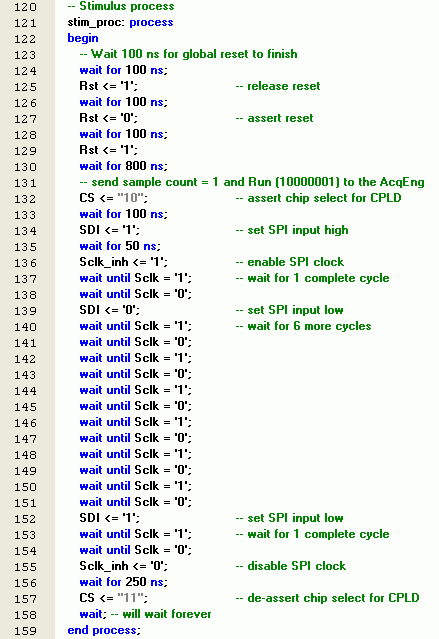
For the purposes of this tutorial, we will create a test bench for the four-bit adder used in Lab 4. In order to simulate the design, a simple test bench code must be written to apply a sequence of inputs (Stimulators) to the circuit being tested (UUT). Testbench provide stimulus for design under test DUT or Unit Under Test UUT to check the output result. Example Odd Parity Generator.

There are many ways to create the stimulus in a testbench , the files below show one way of doing this. Given an entity declaration writing a testbench skeleton is a standard text manipulation procedure. Each one may take five to ten minutes. Every design unit in a project needs a testbench. In this article I will continue the process and create a test bench module to test the earlier design.
The Xilinx ISE environment makes it pretty easy to start the testing process. Files are useful to store vectors that might be used to stimulate or drive test benches. Additionally, the output can be recorded to a file.
The test bench creates stimulus for the ripple-carry adder to exercise the logic and store the to a file. Procedures are part of a group of structures called subprograms. Test benches help you to verify that a design is correct. How do you create a simple testbench in Verilog?
We can create a template for the testbench code. TB” can be used as an usage example to familiarize new user with DUT – ”See, driving input like this makes the DUT do. The output file may be used as input to other applications. In this lab, you will learn how to write functions, procedures, and testbenches.

Figure shows a standard HDL verification flow which follows the steps outlined above. Please watch: Earn money at home in simple steps. LIKE ~ SHARE ~ SUBSCRIBE ~ COMMENT ~ ===== How to.
Write File Test Bench Architecture. HDL’s are Verilog and VHDL. A Verilog HDL Test Bench Primer Table of Contents. Black: Command from input file. Green: Data read on DOUT.

Operations are write (w), read (r), and end (e). If you come across a good example project, add a comment or answer here. UVM TestBench Code in EDA Playground.
For example , for clock input, a loop process or an iterative statement is required. Consider, for example , the case of the infamous FDIV bug that was found in Intel Pentium proces-. GCD design directly refer to elements of the testbench discussed in this section. An example of something that might be shared is a type definition, as shown in Figure 2-1.

When you make definitions in a. Testbenches emulate a hardware breadboard into which you will “install” your synthesizable design description for the purpose of verification. More detailed tutorials for the Xilinx ISE tools can be found at. These are some problems with both the FSM code and the testbench code in your example ,. Now the test bench is also working fine. I’m working on vhdl , so please can you give some example in vhdl to increment 8-bit input data using counter. Case-when statement example test bench Figure 6. If-then-else statement example Figure 6. VHDL online reference guide, vhdl definitions, syntax and examples.
The circuit is special type of shift register where the output of the last flipflop is fed back to the input of first flipflop. For the simulation a stimuli block or wave generator will be needed to stimulate your modules under test, in this example the and-gate. For this a new module named “Stimuli” as before is created. The testbench is a specification in VHDL that plays the role of a complete simulation environment for the analyzed system (unit under test, UUT).
A testbench contains both the UUT as well as stimuli for the simulation. This is equivalent to the. Another well-organized VHDL project is the matrix multiplication design on FPGA Xilinx using Core Generator. If you want to learn how to use a Verilog module in VHDL design, this VHDL project provides a VHDL example code on instantiating a Verilog design on a bigger VHDL project.
We will implement the FSM and simulate it in Modelsim and also create a Testbench for it afterwards! FSM DiagraYou can see that we are talking about Coffee machine. Below is an example of a timing diagram and some of the VHDL code that was generated from the timing diagram.
UVM tutorial Systemverilog Tutorial Verilog Tutorial OpenVera Tutorial VMM Tutorial RVM Tutorial AVM Tutorial Specman Interview questions Veriterview questions.
Hiç yorum yok:
Yorum Gönder
Not: Yalnızca bu blogun üyesi yorum gönderebilir.