Design circuits online in your browser or using the desktop application. A circuit diagram is a visual display of an electrical circuit using either basic images of parts or industry standard symbols. Symbol usage depends on the audience viewing the diagram.

These two different types of circuit diagrams are called pictorial (using basic images) or schematic style (using industry standard symbols). A circuit diagram (also named electrical diagram , elementary diagram , electronic schematic) is a graphical representation of an electrical circuit. A circuit diagram (electrical diagram , elementary diagram , electronic schematic) is a graphical representation of an electrical circuit. A pictorial circuit diagram uses simple images of components, while a schematic diagram shows the components and interconnections of the circuit using standardized symbolic representations.
A circuit diagram would display the inputs according to their sign with respect to the output when a particular input is greater than the other. By using this site, you agree to our use of cookies. A user-friendly program for making electronic circuit diagrams. This work is licensed under a Creative Commons Attribution-NonCommercial 2. Use circuit symbols to construct schematic diagrams for the following circuits: a. A single cell, light bulb and switch are placed together in a circuit such that the switch can be opened and closed to turn the light bulb on. There is a bit difficult to build this kind circuit project, it’s require a good knowledge in electronics.
Tureng Dictionary and Translation Ltd. Kategorilere ayrılmış milyondan fazla sözcük ve sözcükleri farklı aksanlarda dinleme seçeneği. It visualizes the interaction between circuit components, by showing the actual electrical connections. The amplifier circuit diagram shows a 2. You can also make a 5W mono amplifier out of it. A dual potmeter allows you to connect both left and right channel on one potentiometer.
Note that all these links are external and we cannot provide support on the circuits or offer any guarantees to their accuracy. Some circuits would be illegal to operate in most countries and others are dangerous to construct and should not be attempted by the inexperienced. Professional schematic PDFs, wiring diagrams , and plots.
No installation required! Unique circuit URLs let you easily share your work or ask for help online. Bug-free design, excellent simulation. In this project we’ll show you a circuit diagram of smps power supply alongwith description.
A circuit diagram , or a schematic diagram , is a technical drawing of how to connect electronic components to get a certain function. Each electronic component has a symbol. After seeing a few circuit diagrams , you’ll quickly learn how to distinguish the different symbols. This articles shows how to read circuit diagrams for beginners in electronics.

Learn to read electrical and electronic circuit diagrams or schematics. A drawing of an electrical or electronic circuit is known as a circuit diagram , but can also be called a schematic diagram , or just schematic. Code For Ultrasonic Sensor Using Arduino. Identify what the symbols in the circuit diagrams stand for. The important thing to note on this diagram is what everything stands for.
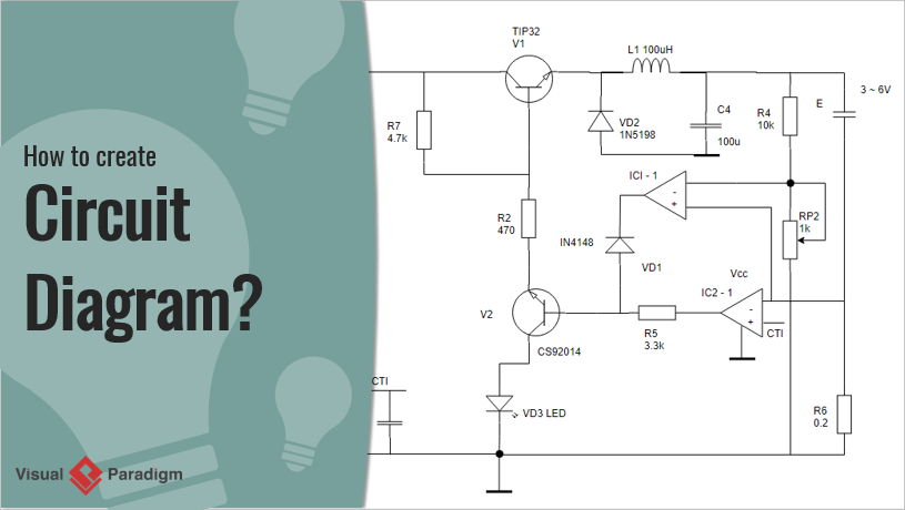
Here is an example circuit diagram. There are 1circuit schematics available in this category. Click here for all circuit diagrams.
Please note some adblockers will suppress the schematics as well as the advertisement so please disable if the schematic list is empty. Mono-stable multivibrator circuit generates a fixed pulse width when receiving a trigger signal on its input. Easy amplifier circuit diagram using D7only: We are going to make an easy amplifier circuit diagram using the only d7transistor. The full adder circuit diagram add three binary bits and gives result as Sum, Carry out. Complete tutorials with diagrams.
The circuit diagram above is quite a typical PLC circuit arrangement. Circuit diagramming has never been easier! That is why instructions for projects usually include a circuit diagram as well as the stripboard or printed circuit board layout which you need to build the circuit. Scheme-it is a free online schematic drawing tool that will allow you to produce professional looking schematic diagrams , add corresponding part numbers, and share your schematic with others. We have searched the web to help you find quick design ideas.

Please let us if you would like us to link to or post your design. Our circuit diagram symbol library is schematic and includes many icons commonly used by engineers. This circuit is constructed to give bit binary counting.
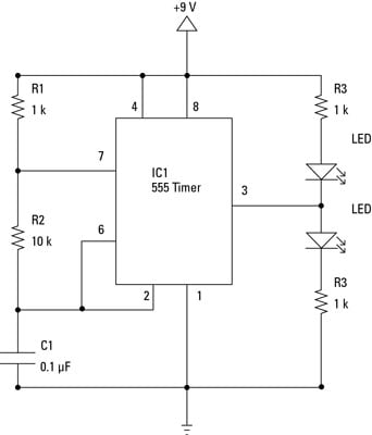
First stage of this circuit is clock generating circuit which is made by timer IC 5and it is configured in Astable multivibrator and provides constant square wave at its output pin 3. This is a low cost 1Watt amplifier circuit with diagram and schematic design using two Darlington power transistors TIP 1and TIP 147. This amplifier circuit can deliver 1Watt RMS. A first look at a circuit diagram may be confusing, but if you can read a subway map, you can read schematics. Literally, a circuit is the path that allows electricity to flow.
The purpose is the same: getting from point A to point B. Diagramly) is free online diagram software.
Hiç yorum yok:
Yorum Gönder
Not: Yalnızca bu blogun üyesi yorum gönderebilir.