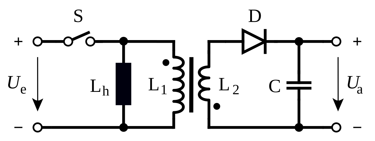
Aşağıdaki şekilde görüldüğü gibi anahtar ilk kapatıldığında akım Lm üzerinden akar. Flyback transformer design considerations! Its derivation is illustrated in Fig. Bu nedenle flyback dönüştürücüler genellikle çıkış geriliminin yüksek olması gereken fakat yüksek güç gerektirmeyen uygulamalarda kullanılırlar. In its various implementations including primary side and secondary side regulation, fixed switching frequency or quasi resonant operation, an isolated or non-isolated flyback topology is most often found in off-line converters for an output power ranging from a few watts up to 1W.
Now that the topology ( flyback ) and control method (peak current mode control) have been decided upon, the next decision to be made is what the maximum duty cycle, Dmax, should be. With multiple output windings, it is possible to provide both higher and lower voltage outputs simultaneously. While it looks superficially like a flyback converter, it operates in a fundamentally. A flyback converter is a simple switch-mode power supply.
Biraz daha güzel açıklarsam, DC bir gerilimi başka bir DC gerilime çevirmeye yarayan ve giriş-çıkış arasında galvanik izolasyon sağlayan en basit çevirici devre tiplerinden birisidir. In practice the voltage is even higher because an induction voltage is added as a result of transformer leakage induction. Saliva Infineon Technologies North America (IFNA) Corp. It has two modes of operation namely mode-and mode-2.

Actually this is the big advantage of a flyback converter over a boost converter. In a boost converter the switch (MOSFET) has to carry a large current during the on phase and a high voltage during the off phase. Der Sperrwandler, auch Hoch-Tiefsetzsteller, englisch flyback converter , ist eine Bauform von Gleichspannungswandlern. Er dient zur Übertragung elektrischer Energie zwischen einer Eingangs- und einer Ausgangsseite galvanisch getrennter Gleichspannungen. We now briefly discuss the operation of the flyback converter.
The underlying circuit is a PWM flyback converter , running in continuous mode. First of all, when the MOSFET turns on, given that the polarity of the transformer is reverse a current flows to the primary winding of the transformer, where energy is stored. Now, it turns out that in the buck boost.

And have a point in the middle of the. The operating principle is similar to the buck-boost converter , but an additional transformer is used to achieve galvanic isolation of the input and output. The proposed power supply designed using flyback converter topology that is controlled by the critical conduction mode control.
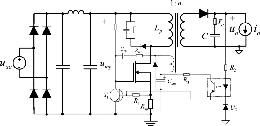
By sampling the isolated output voltage directly from the primary-side flyback waveform, the part requires no third winding or opto-isolator for regulation. When the power switch is on, the flyback converter stores energy in the primary-side inductor. During the switch off time, the energy transfers to the secondary and from there to the output.
The transformer has a primary winding at a first side. The active snubber is coupled in parallel with two ends of the primary winding and has a first circumferential circuit coupling in parallel with the primary winding, a second circumferential circuit and a zero voltage switch unit. In this paper, a flyback converter was designed considering the specified design criteria. Primary side sensing ” technique.
Analysis of the designed. One of the most important factors in the design of a flyback converter power supply is the design of the. Technical Information Site of Power Supply Design. To simplify circuit analysis, we can convert the flyback circuit to a basic buck-boost converter configuration. The conversion can be done in two steps: Step one: converting all outputs into a single output.
Transfer of DC current via transformer 4. Voltage transfer function. Typical flyback transformer circuit. All SMPS are prone to glitches and ringing, but flybacks are especially notorious — and especially in DCM. The flyback regulator can operate in either discontinuous or continuous mode. You can also see that the output voltage has gone up significantly, same as with a boost converter in DCM.
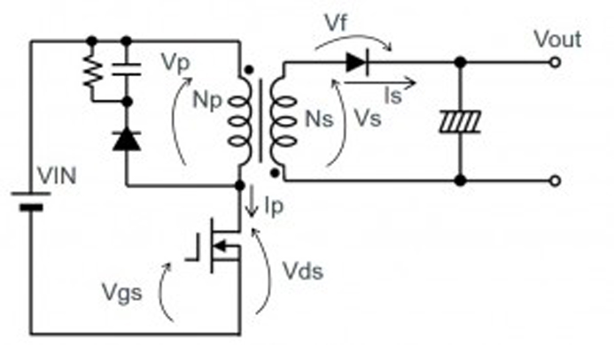
The figure shows the circuit diagram of flyback converter. Observe the dot conventions on the transformer primary and secondary. Conclusion By adding a high side MOSFET switch, the two-switch forward or flyback topology clamps the volt-age stress on each MOSFET switch to the input voltage. This application note explains the key steps in designing two of the most important components in a flyback converter - the transformer and the snubber resistor. Figure 1: Functional diagram of a flyback converter using a single MOSFET switch and a flyback transformer.
Image source: Digi-Key Electronics) The chief advantage of the flyback topology is its simplicity. In a two-switch flyback topology, a high-side power MOSFET – placed between the input voltage rail and the transformer – and snubber diode are added to help overcome the limitations of conventional flyback topology as the overall voltage stress is equally split between the two transistors. The overshoot on the transistor voltage, is due to the leakage inductance, $ L_k $, of the transformer.
P_s $ - max power dissipated by the snubber resistor $ R_s $ - snubber resistor $ C_s $. To some extent the flyback converter can be seen as an isolated buck-boost converter. Following this approach the buck-boost inductor split is to form a transformer, so that the voltage ratios. The two-switch flyback DC–DC converter is an extended version of the conventional single-switch flyback converter. The basic components of the switching circuit can be rearranged to form a step-down (buck) converter , a step-up (boost) converter , or an inverter ( flyback ). These designs are shown in Figures , , , and respectively, where Figures and are the same except for the transformer and the diode polarity.

For flyback coverters, the transformer is the most important factor that determines the performance such as the efficiency, output regulation and EMI. Contrary to the normal transformer, the flyback transformer is inherently an inductor that provides energy storage, coupling and isolation for the flyback converter. SWITCHING POWER SUPPLY DESIGN: CONTINUOUS MODE FLYBACK CONVERTER Written by Michele Sclocchi michele.
These can be classified according to isolation and regulation requirements as follows: 1. This product guarantees long time.
Hiç yorum yok:
Yorum Gönder
Not: Yalnızca bu blogun üyesi yorum gönderebilir.